The DC input, DC output LVDT is an AC LVDT with an integral oscillator/demodulator, providing a compact and cost-effective means of sensing displacement. The
the following explains how to create simple, passive signal conditioning circuits to scale, offset, and allow fine adjustment of zero for a standard, bipolar LVDT.
Power Supply
DC-DC LVDTs are designed to be excited by a regulated DC power supply. The transducer’s output will track any change in the excitation voltage. As a general recommendation, power supply line and load regulations should be better than 0.1%. However, the power supply stability should be consistent with the system accuracy requirements.
Because of the varying current draw of the oscillator, the power supply should have a current capacity at least twice the nominal value specified for the transducer. A lesser rating may compromise system linearity. When multiple LVDTs are to operate from the same power supply, they should all be connected directly to the supply and not to a common remote junction. This will reduce the possibility of crosstalk between the units. In addition, the varying current draw of individual units through the resistance of common power leads may cause local voltage drops at the LVDT, which will, in turn, produce unstable outputs.
Signal Conditioning
The output of a DC-DC LVDT is bipolar. At one end of the linear range, the output will be a negative DC voltage; in the middle, zero volts; and at the other end, a positive DC voltage. To gain more flexibility and control of the output characteristics, passive signal conditioning may be used. The three primary functions of the signal processing are: scaling the output signal, electrical zero adjustment, and converting the output to a unipolar voltage. These functions can be addressed separately, but are oftentimes combined in a zero offsetting and scaling circuit.
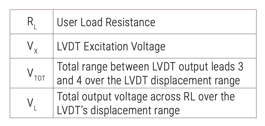
Common Terms Used In The Following Examples Are:
Output Scaling
The connections necessary to scale the output of the LVDT are illustrated in Figure 1.
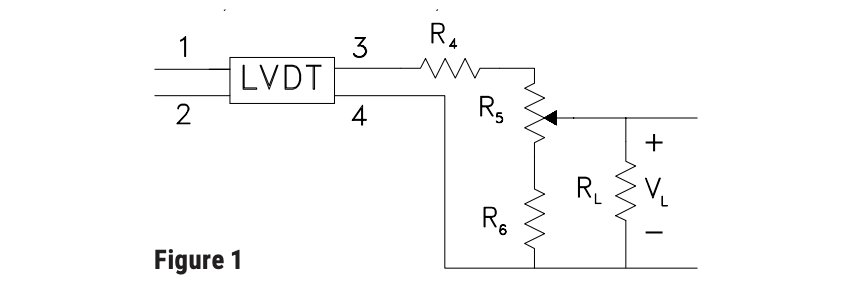
The fixed resistors, R4 and R6, are used for stability, while the potentiometer R5 is used for adjusting VL. For very large values of RL {RL>10(R5 + 2R6)} the ratio of VL to VTOT is approximated by:

The load (L) seen by the LVDT should be kept above 100K Ohms to minimize the effect on linearity, and is defined as:

R5, which is usually selected to provide 20% adjustment of VL, which reduces to:

Combining the above formula to solve for R5 yields:

R4 is the sum of the LVDT output impedance given in LVDT specifications, and a resistor added by the user.
Zero Adjustment
In some applications, it is necessary to have an electrical means of fine adjustment of the transducer’s Zero output. Zero adjustment ranges greater than 10% of VL may allow the unit to operate in a nonlinear region of travel. It is further recommended that the sum of the voltage divider should be less than 1 kOhms to minimize the zero shift of the output when the load resistance, RL, changes. These recommendations result in the following formulas and the schematic in Figure 2.
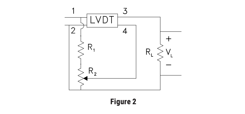
To use this configuration effectively, secure the LVDT so that the VL is nearly zero when the mechanism monitored by the LVDT is at its exact center of travel. R2 can then be adjusted to make the output voltage across VL exactly zero.
Unipolar Output, With Zero Adjustment
The zero adjusting technique described previously can be used to provide a unipolar output as well as zero adjustment as described in Figure 3. Adding a resistor R3, between R2 and pin 2, results in the following formulas.
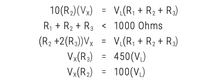
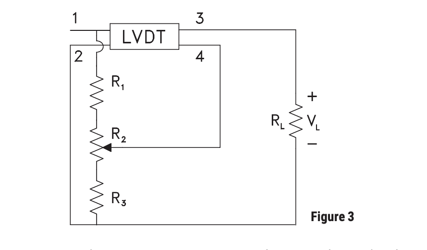
Again, use the same set up procedure as described in the Zero Adjustment section.
Complete Signal Conditioning
Figure 4 shows a combined the scaling, offsetting, and zero adjustment circuit will give us a fully functional signal conditioner for a DC-DC LVDT.

In conclusion, the DC-DC LVDT can be used with a very simple, passive circuit to provide DC output voltages scaled to meet the users exact needs. If there are any additional questions about signal conditioning alternatives, please contact your local representative, or a Trans-Tek Applications Engineer.